
4.ADC采样测试
该教程演示如何通过开发板的GPIO实现ADC采样
一、准备工作
- 准备1块BearPi-Pico H3863开发板
二、编译代码
在Windows下编译操作
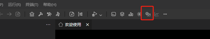
点击工具栏中的“系统配置”,打开配置界面.
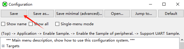
选择Support ADC Sample.
Application  --->
    [*] Enable Sample.
    [*]     Enable the Sample of peripheral.
    [ ]         Enable all the sample of peripheral, it's just for build.
    [*]         Support ADC Sample.
                    ADC Sample Configuration  ----
按下"Save"键保存配置。
在代码中设置采样通道。
目前仅GPIO7、8、9、10、11、12支持ADC,分别对应通道0~5,此处以通道0为例,对应GPIO7
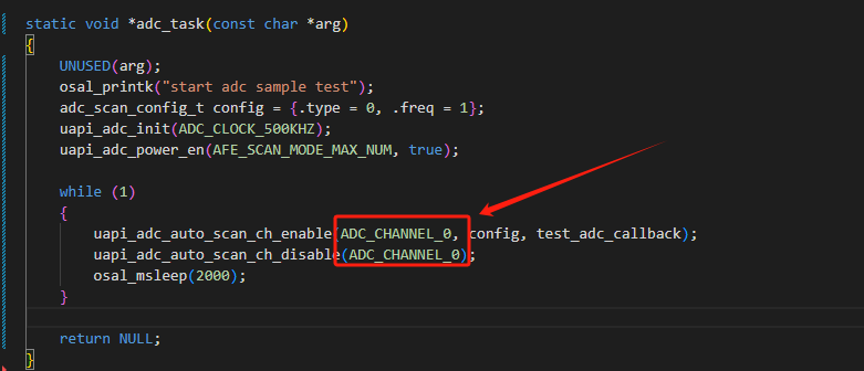
关键代码,位于
application\samples\peripheral\adc\adc_demo.cstatic void *adc_task(const char *arg) { UNUSED(arg); osal_printk("start adc sample test"); adc_scan_config_t config = {.type = 0, .freq = 1}; uapi_adc_init(ADC_CLOCK_500KHZ); //初始化ADC uapi_adc_power_en(AFE_SCAN_MODE_MAX_NUM, true); //使能ADC while (1) { uapi_adc_auto_scan_ch_enable(ADC_CHANNEL_0, config, test_adc_callback); //使能ADC通道中断 uapi_adc_auto_scan_ch_disable(ADC_CHANNEL_0); //去使能ADC通道中断 osal_msleep(2000); } return NULL; }编译烧录固件
参考环境搭建教程编译烧录代码
在Ubuntu下编译操作
在MobaXterm中输入:
./build.py menuconfig ws63-liteos-app选择Support ADC Sample.
Application  --->
    [*] Enable Sample.
    [*]     Enable the Sample of peripheral.
    [ ]         Enable all the sample of peripheral, it's just for build.
    [*]         Support ADC Sample.
                    ADC Sample Configuration  ----
按下"ESC"键退出并保存配置。
在代码中设置采样通道。
目前仅GPIO7、8、9、10、11、12支持ADC,分别对应通道0~5,此处以通道0为例,对应GPIO7
关键代码,位于
application\samples\peripheral\adc\adc_demo.cstatic void *adc_task(const char *arg) { UNUSED(arg); osal_printk("start adc sample test"); adc_scan_config_t config = {.type = 0, .freq = 1}; uapi_adc_init(ADC_CLOCK_500KHZ); //初始化ADC uapi_adc_power_en(AFE_SCAN_MODE_MAX_NUM, true); //使能ADC while (1) { uapi_adc_auto_scan_ch_enable(ADC_CHANNEL_0, config, test_adc_callback); //使能ADC通道中断 uapi_adc_auto_scan_ch_disable(ADC_CHANNEL_0); //去使能ADC通道中断 osal_msleep(2000); } return NULL; }编译烧录固件
参考环境搭建教程编译烧录代码
三、测试
烧录固件后按下开发的复位按键,用杜邦线将GPIO02与GND或者V3.3脚短接,观察电压变化
channel: 0, voltage: 1mv
channel: 0, voltage: 1mv
channel: 0, voltage: 1mv
channel: 0, voltage: 3300mv
channel: 0, voltage: 3300mmv
channel: 0, voltage: 3300mmv

